Burton Unions: Difference between revisions
No edit summary |
No edit summary |
||
| (4 intermediate revisions by 2 users not shown) | |||
| Line 6: | Line 6: | ||
<gallery> | <gallery> | ||
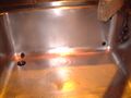
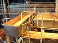
File:DSCF0010.JPG|<small>At Marstons the fermentation is pitched at 14<sup>o</sup>C in an enclosed square situated at the side of the Union Room (to the top right). Once the fermentation reaches top heat of around 19<sup>o</sup>C after some 36 hours, the fermenting wort is transferred into the Burton set. | File:DSCF0010.JPG|<small>At Marstons the fermentation is pitched at 14<sup>o</sup>C in an enclosed square situated at the side of the Union Room (to the top right). Once the fermentation reaches top heat of around 19<sup>o</sup>C after some 36 hours, the fermenting wort is transferred into the Burton set.</small> | ||
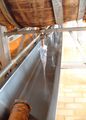
File:DSCF0011a.JPG|A true cathedral of beer, there is nothing else like it in the world. | File:DSCF0011a.JPG|<small>A true cathedral of beer, there is nothing else like it in the world.</small> | ||
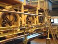
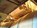
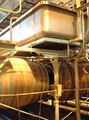
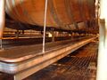
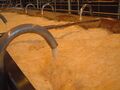
File:DSCF0012.JPG|A set comprises banks of 7hL unlined wooden casks, a unit of 26 casks (13 in two rows) would total a 100 barrel batch. There is a tap in the belly of the cask and opposite, a hole which takes a swans neck. This tube directs the fermentation froth from the cask into a trough which runs the length of the set at high level between the casks. | File:DSCF0012.JPG|<small>A set comprises banks of 7hL unlined wooden casks, a unit of 26 casks (13 in two rows) would total a 100 barrel batch. There is a tap in the belly of the cask and opposite, a hole which takes a swans neck. This tube directs the fermentation froth from the cask into a trough which runs the length of the set at high level between the casks. </small> | ||
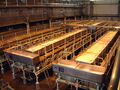
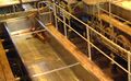
File:DSCF0013a.JPG|A view of a union set in the Alpin Room | File:DSCF0013a.JPG|<small>A view of a union set in the Alpin Room.</small> | ||
File:DSCF0014a.JPG|Marstons has raised the pivot point above the wooden frames to make it easier to remove the casks for overhaul | File:DSCF0014a.JPG|<small>Marstons has raised the pivot point above the wooden frames to make it easier to remove the casks for overhaul.</small> | ||
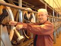
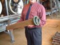
File:DSCF0015.JPG|Head Brewer Paul Bayley gives some scale to the 7hL casks | File:DSCF0015.JPG|<small>Head Brewer Paul Bayley gives some scale to the 7hL casks.</small> | ||
File:DSCF0016.JPG|The whole weight of over a tonne bears down on the bottom stave weakened by the aperture for the tap. | File:DSCF0016.JPG|<small>The whole weight of over a tonne bears down on the bottom stave weakened by the aperture for the tap.</small> | ||
File:DSCF0017b.JPG|This picture from the old Bass Museum shows the fermenting records of double set 3 and 4. The attenuation is shown in the column headed A. You can see when the top trough attemperators were turned on and later the casks | File:DSCF0017b.JPG|<small>This picture from the old Bass Museum shows the fermenting records of double set 3 and 4. The attenuation is shown in the column headed A. You can see when the top trough attemperators were turned on and later the casks.</small> | ||
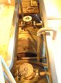
File:DSCF0018.JPG|Another photo from the Bass Museum shows the valve which controls the flow from the feeder back into the casks. The large bore is used for filling the casks at the start of the process and the smaller bypass is used during fermentation. | File:DSCF0018.JPG|<small>Another photo from the Bass Museum shows the valve which controls the flow from the feeder back into the casks. The large bore is used for filling the casks at the start of the process and the smaller bypass is used during fermentation.</small> | ||
File:DSCF0019.JPG|At Marstons a calibrated diaphragm valve does the same job | File:DSCF0019.JPG|<small>At Marstons a calibrated diaphragm valve does the same job.</small> | ||
File: | File:DSCF0020b.JPG|<small>Detail of a cask head. The feeder arm is at the top to fill the casks and allow collapsed fob to return, on the right is the sample tap - only one per side of 13 casks. The flexible tubes run cooling water to the cask attemperators. The iron cross supports the cask on the frame. The cask is clamped into position but released for cleaning by attaching a crank to the trunnion stub.</small> | ||
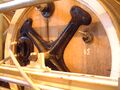
File: | File:DSCF0020a.JPG|<small>A close up of the iron cross and trunnion.</small> | ||
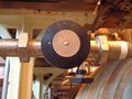
File:DSCF0021.JPG|The valve controlling the flow to the cask attemperator | File:DSCF0021.JPG|<small>The valve controlling the flow to the cask attemperator.</small> | ||
File:DSCF0026a.JPG|Detail of three cask heads | File:DSCF0026a.JPG|<small>Detail of three cask heads.</small> | ||
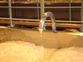
File:DSCF0029.JPG|Head Brewer Paul Bayley takes a sample | File:DSCF0029.JPG|<small>Head Brewer Paul Bayley takes a sample.</small> | ||
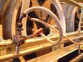
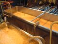
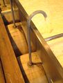
File:DSCF0068.JPG|The trough slopes gently towards a transverse ‘feeder’ and from there collapsed fob is fed back into each cask. During cleansing, the yeast settles out in the top trough and the beer weirs into the feeder though valved connecting pipes. | File:DSCF0068.JPG|<small>The trough slopes gently towards a transverse ‘feeder’ and from there collapsed fob is fed back into each cask. During cleansing, the yeast settles out in the top trough and the beer weirs into the feeder though valved connecting pipes.</small> | ||
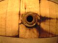
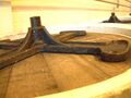
File:DSCF0069.JPG| | File:DSCF0069.JPG|<small>Viewed from the top trough looking towards the feeder; the hole on the top right feeds the collapsed fob back into the feeder trough. The bottom left empties the trough at the end of fermentation and the larger hole in the base is used to remove the yeast crop.</small> | ||
File:DSCF0069a.JPG|The connections from the trough to the feeder on the right | File:DSCF0069a.JPG|<small>The connections from the trough to the feeder on the right. The small pipe entering the feeder is part of the cleaning circuit.</small> | ||
File:DSCF0069b.JPG|<small>The view of the connections to the feeder from below.</small> | |||
File: | File:DSCF0069c.JPG|<small>The trough (below left) and feeder trough.</small> | ||
File: | File:DSCF0069d.JPG|<small>Note the safety features of the Marstons sets.</small> | ||
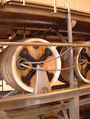
File: | File:DSCF0070.JPG|<small>The circulation of fob is driven by a 1<sup>o</sup>C temperature differential by applying cooling to panels in the top trough. This set under repair shows the cooling surface on the bottom of the trough.</small> | ||
File:DSCF0071.JPG|<small>There are water cooled coils in each cask to lower the temperature before racking. Head Brewer Paul Bayley demonstrates.</small> | |||
File: | File:DSCF0072.JPG|<small>When racking gravity is reached there is a crop of yeast in the trough and the cask has a yeast count in the order of one million cells. Remaining beer in the top trough is run to an empty cask in the set and the yeast is manually removed to a waiting trolley before transfer to cold storage. </small> | ||
File:DSCF0072a.JPG|<small>A bottom trough runs the length of the set under each row of casks to empty them.</small> | |||
File:DSCF0074.JPG|<small>The beer is racked from the casks by opening the taps below each cask. The tap is fitted with a plastic bag secured with a rubber band and the beer flows into a bottom trough with a minimum of fobbing. The trough empties by gravity and is fed to the racking vessels. Some 3 litres of ‘grounds’ held back in the cask by the length of the tap are run to waste before cleaning.</small> | |||
File:DSCF0074a.jpg|How Bass managed yeast counts and losses. This shows a bottom tap and the cask bottom boss. The left hand has been laboriously manually wound out '16 threads' as there is likely to be only a small volume of yeast in the belly of the cask. Latterly yeast counts were taken from the cask before racking. The right hand example shows the tap fully in to accommodate the full 3L which Marstons leave behind as a loss. | File:DSCF0074a.jpg|<small>How Bass managed yeast counts and losses. This shows a bottom tap and the cask bottom boss. The left hand has been laboriously manually wound out '16 threads' as there is likely to be only a small volume of yeast in the belly of the cask. Latterly yeast counts were taken from the cask before racking. The right hand example shows the tap fully in to accommodate the full 3L which Marstons leave behind as a loss.</small> | ||
File:DSCF0075.JPG|There is still a full time cooper on site with enough seasoned oak to last for a while | File:DSCF0075.JPG|<small>There is still a full time cooper on site with enough seasoned oak to last for a while.</small> | ||
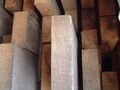
File:DSCF0076.JPG|The stock of timber in the brewery yard | File:DSCF0076.JPG|<small>The stock of timber in the brewery yard.</small> | ||
File:DSCF0077.JPG|There is nothing quite so satisfying in the world of brewing as being able to watch the steady plopping of a union set in quiet execution is its cleansing duties except perhaps the enjoyment of a glass of Pedigree it produces. | File:DSCF0077.JPG|<small>There is nothing quite so satisfying in the world of brewing as being able to watch the steady plopping of a union set in quiet execution is its cleansing duties except perhaps the enjoyment of a glass of Pedigree it produces.</small> | ||
File:DSCF0078.JPG|Still plopping | File:DSCF0078.JPG|<small>Still plopping.</small> | ||
File:DSCF0079a.JPG|Even more plopping | File:DSCF0079a.JPG|<small>Even more plopping.</small> | ||
File:DSCF0080a.JPG|Allan Alpin was Head Brewer and Director from 1967 to 1992. His name is used on one of Marstons two Union Rooms | File:DSCF0080a.JPG|<small>Allan Alpin was Head Brewer and Director from 1967 to 1992. His name is used on one of Marstons two Union Rooms.</small> | ||
File:DSCF0081a.JPG|Allan Alpin's memorial comprising a cask head with a racking tap inserted at 12 o'clock. | File:DSCF0081a.JPG|<small>Allan Alpin's memorial comprising a cask head with a racking tap inserted at 12 o'clock.</small> | ||
File:tbass unions 1.jpg|The Bass unions from the walkway. There were 30 double (200brl) sets, here two sets shared a single feeder trough. | File:tbass unions 1.jpg|<small>The Bass unions from the walkway. There were 30 double (200brl) sets, here two sets shared a single feeder trough.</small> | ||
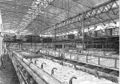
File:tbass unions 2.jpg|A shot of the Bass Union Room with some of its 1,560 casks which closed in April 1982. Jim Bakewell, the foreman is replacing the swans necks | File:tbass unions 2.jpg|<small>A shot of the Bass Union Room with some of its 1,560 casks which closed in April 1982. Jim Bakewell, the foreman is replacing the swans necks.</small> | ||
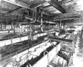
File:trumans unions.jpg|From Alfred Barnard in the late 1880s - Trumans in Burton - note the swans neck pass through the top trough | File:trumans unions.jpg|<small>From Alfred Barnard in the late 1880s - Trumans in Burton - note the swans neck pass through the top trough.</small> | ||
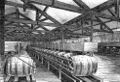
File:walkers unions.jpg|From Alfred Barnard in the late 1880s - A B Walker in Burton | File:walkers unions.jpg|<small>From Alfred Barnard in the late 1880s - A B Walker in Burton.</small> | ||
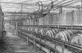
File:wardwick unions.jpg|From Alfred Barnard in the late 1880s - a single sided set at the Wardwick Brewery in Derby | File:wardwick unions.jpg|<small>From Alfred Barnard in the late 1880s - a single sided set at the Wardwick Brewery in Derby.</small> | ||
File:youngers unions.jpg|From Alfred Barnard in the late 1880s - Youngers in Edinburgh also used Burton Unions. | File:youngers unions.jpg|<small>From Alfred Barnard in the late 1880s - Youngers in Edinburgh also used Burton Unions. | ||
</small> | </small> | ||
</gallery> | </gallery> | ||
[[category:Brewer & Distiller International Gallery]] | [[category:Brewer & Distiller International Gallery]] | ||
Latest revision as of 17:07, 15 June 2016
Introduction
The Burton Union method of fermentation is essentially a ‘cleansing’ system. It is a means of removing yeast from beer as the fermentation finishes as well as collecting it for use in subsequent brews. It particularly suits the rather powdery strains traditional in Burton on Trent as the sedimentation distance is a matter of inches and not metres. Only Pedigree and Owd Rodger strong ale go through the union sets at Burton. About 40% of the Pedigree destined for cask sale is fermented to completion in squares and is blended with union beer before packaging.
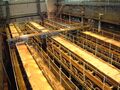
At Marstons the fermentation is pitched at 14oC in an enclosed square situated at the side of the Union Room (to the top right). Once the fermentation reaches top heat of around 19oC after some 36 hours, the fermenting wort is transferred into the Burton set.
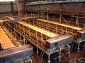
A true cathedral of beer, there is nothing else like it in the world.
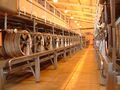
A set comprises banks of 7hL unlined wooden casks, a unit of 26 casks (13 in two rows) would total a 100 barrel batch. There is a tap in the belly of the cask and opposite, a hole which takes a swans neck. This tube directs the fermentation froth from the cask into a trough which runs the length of the set at high level between the casks.
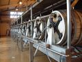
A view of a union set in the Alpin Room.
Marstons has raised the pivot point above the wooden frames to make it easier to remove the casks for overhaul.
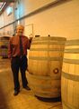
Head Brewer Paul Bayley gives some scale to the 7hL casks.
The whole weight of over a tonne bears down on the bottom stave weakened by the aperture for the tap.
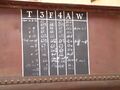
This picture from the old Bass Museum shows the fermenting records of double set 3 and 4. The attenuation is shown in the column headed A. You can see when the top trough attemperators were turned on and later the casks.
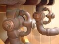
Another photo from the Bass Museum shows the valve which controls the flow from the feeder back into the casks. The large bore is used for filling the casks at the start of the process and the smaller bypass is used during fermentation.
At Marstons a calibrated diaphragm valve does the same job.
Detail of a cask head. The feeder arm is at the top to fill the casks and allow collapsed fob to return, on the right is the sample tap - only one per side of 13 casks. The flexible tubes run cooling water to the cask attemperators. The iron cross supports the cask on the frame. The cask is clamped into position but released for cleaning by attaching a crank to the trunnion stub.
A close up of the iron cross and trunnion.
The valve controlling the flow to the cask attemperator.
Detail of three cask heads.
Head Brewer Paul Bayley takes a sample.
The trough slopes gently towards a transverse ‘feeder’ and from there collapsed fob is fed back into each cask. During cleansing, the yeast settles out in the top trough and the beer weirs into the feeder though valved connecting pipes.
Viewed from the top trough looking towards the feeder; the hole on the top right feeds the collapsed fob back into the feeder trough. The bottom left empties the trough at the end of fermentation and the larger hole in the base is used to remove the yeast crop.
The connections from the trough to the feeder on the right. The small pipe entering the feeder is part of the cleaning circuit.
The view of the connections to the feeder from below.
The trough (below left) and feeder trough.
Note the safety features of the Marstons sets.
The circulation of fob is driven by a 1oC temperature differential by applying cooling to panels in the top trough. This set under repair shows the cooling surface on the bottom of the trough.
There are water cooled coils in each cask to lower the temperature before racking. Head Brewer Paul Bayley demonstrates.
When racking gravity is reached there is a crop of yeast in the trough and the cask has a yeast count in the order of one million cells. Remaining beer in the top trough is run to an empty cask in the set and the yeast is manually removed to a waiting trolley before transfer to cold storage.
A bottom trough runs the length of the set under each row of casks to empty them.
The beer is racked from the casks by opening the taps below each cask. The tap is fitted with a plastic bag secured with a rubber band and the beer flows into a bottom trough with a minimum of fobbing. The trough empties by gravity and is fed to the racking vessels. Some 3 litres of ‘grounds’ held back in the cask by the length of the tap are run to waste before cleaning.
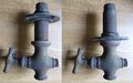
How Bass managed yeast counts and losses. This shows a bottom tap and the cask bottom boss. The left hand has been laboriously manually wound out '16 threads' as there is likely to be only a small volume of yeast in the belly of the cask. Latterly yeast counts were taken from the cask before racking. The right hand example shows the tap fully in to accommodate the full 3L which Marstons leave behind as a loss.
There is still a full time cooper on site with enough seasoned oak to last for a while.
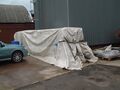
The stock of timber in the brewery yard.
There is nothing quite so satisfying in the world of brewing as being able to watch the steady plopping of a union set in quiet execution is its cleansing duties except perhaps the enjoyment of a glass of Pedigree it produces.
Still plopping.
Even more plopping.
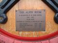
Allan Alpin was Head Brewer and Director from 1967 to 1992. His name is used on one of Marstons two Union Rooms.
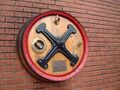
Allan Alpin's memorial comprising a cask head with a racking tap inserted at 12 o'clock.
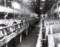
The Bass unions from the walkway. There were 30 double (200brl) sets, here two sets shared a single feeder trough.
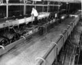
A shot of the Bass Union Room with some of its 1,560 casks which closed in April 1982. Jim Bakewell, the foreman is replacing the swans necks.
From Alfred Barnard in the late 1880s - Trumans in Burton - note the swans neck pass through the top trough.
From Alfred Barnard in the late 1880s - A B Walker in Burton.
From Alfred Barnard in the late 1880s - a single sided set at the Wardwick Brewery in Derby.
From Alfred Barnard in the late 1880s - Youngers in Edinburgh also used Burton Unions.


