Carlsberg Tetley, Northampton - Gallery: Difference between revisions
(Created page with "DSCF3899 The brewery was opened in 1974 DSCF3900 The brewery was designed to incorporate the shape of a viking longboat - the prow is the brewhouse DSCF3901 Corporate offi...") |
m (Bhadmin moved page Carlsberg Tetley, Northampton - photographs taken by Roger Putman - 17 September 2003 to Carlsberg Tetley, Northampton - Gallery without leaving a redirect) |
||
| (10 intermediate revisions by 2 users not shown) | |||
| Line 1: | Line 1: | ||
DSCF3899 The brewery was opened in 1974 | |||
DSCF3900 The brewery was designed to incorporate the shape of a viking longboat - the prow is the brewhouse | <gallery> | ||
DSCF3901 Corporate offices on site | File:DSCF3899.JPG|The brewery was opened in 1974 | ||
DSCF3902 Road tanker loading bay | File:DSCF3900.JPG|The brewery was designed to incorporate the shape of a viking longboat - the prow is the brewhouse | ||
DSCF3903 Another view of road tankers | File:DSCF3901.JPG|Corporate offices on site | ||
DSCF3988 The bare concrete does present a rather austere facade | File:DSCF3902.JPG|Road tanker loading bay | ||
DSCF3989 Steam issues from the viking longboat! | File:DSCF3903.JPG|Another view of road tankers | ||
DSCF3990 Two malt silos. One has nine 100 tonne cells and other six 200t | File:DSCF3988.JPG|The bare concrete does present a rather austere facade | ||
DSCF3991 Malt wagon unloading | File:DSCF3989.JPG|Steam issues from the viking longboat! | ||
DSCF3992 The chisel bottom of the silo cells in created by a huge conical bottom to the structure | File:DSCF3990.jpg|Two malt silos. One has nine 100 tonne cells and other six 200t | ||
DSCF3993 The outfeed conveyors from the malt silos | File:DSCF3991.JPG|Malt wagon unloading | ||
DSCF3999 | File:DSCF3992.JPG|The chisel bottom of the silo cells in created by a huge conical bottom to the structure | ||
DSCF4001 60% of the beer bitterness comes from liquid extract. It is kept warm in a Decker cabinet. | File:DSCF3993.JPG|The outfeed conveyors from the malt silos | ||
DSCF4002 The extract is tipped from a drum into the working tank | File:DSCF3999.JPG|CO<sub>2</sub> collection plant by Union Engineering from Denmark | ||
DSCF4003 This device slits hop pellet boxes - it was awaiting its cabinet | File:DSCF4001.JPG|60% of the beer bitterness comes from liquid extract. It is kept warm in a Decker cabinet. | ||
DSCF4004 Hop pellets are fed into the hop pots. Wort picks them up and pumps the hops to the coppers | File:DSCF4002.JPG|The extract is tipped from a drum into the working tank | ||
DSCF4007 Another treatments pot | File:DSCF4003.JPG|This device slits hop pellet boxes - it was awaiting its cabinet | ||
DSCF4008 Inside the cavernous brewhouse | File:DSCF4004.JPG|Hop pellets are fed into the hop pots. Wort picks them up and pumps the hops to the coppers | ||
DSCF4022 The malt screens are by Buhler | File:DSCF4007.JPG|Another treatments pot | ||
DSCF4023 The Chronos Richardson malt weighers | File:DSCF4008.JPG|Inside the cavernous brewhouse | ||
DSCF4024 The hammer mill within its acoustic and explosion proof box | File:DSCF4022.JPG|The malt screens are by Buhler | ||
DSCF4025 This 12 tonne Meura mash filter was installed in 1998 | File:DSCF4023.JPG|The Chronos Richardson malt weighers | ||
DSCF4026 The wort balance tank on the Meura mash filter | File:DSCF4024.JPG|The hammer mill within its acoustic and explosion proof box | ||
DSCF4031 The newer mash filter installed in 2002 | File:DSCF4025.JPG|This 12 tonne Meura mash filter was installed in 1998 | ||
DSCF4034 Below the mash filter showing the spent grains discharge | File:DSCF4026.JPG|The wort balance tank on the Meura mash filter | ||
DSCF4035 The discharge to the spent grains tanks | File:DSCF4031.JPG|The newer mash filter installed in 2002 | ||
DSCF4036 High above the brew vessels | File:DSCF4034.JPG|Below the mash filter showing the spent grains discharge trough | ||
File:DSCF4035.JPG|The discharge to the spent grains tanks | |||
DSCF4047 Bare concrete walls in the brewhouse | File:DSCF4036.JPG|High above the brew vessels | ||
DSCF4055 The copper calandria by Huppmann | File:DSCF4045.JPG|The two mash filters are at right angles to each other | ||
DSCF4058 Taking a wort sample | File:DSCF4047.JPG|Bare concrete walls in the brewhouse | ||
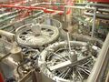
DSCF4062 The vessel in the foreground is the whirlpool with the wort prerun vessel behind | File:DSCF4055.JPG|The copper calandria by Huppmann | ||
DSCF4068 The whirlpool vessel | File:DSCF4058.JPG|Taking a wort sample | ||
DSCF4070 The mash vessel will process 12 tonnes every two hours giving twelve 650hL brews a day. There are two mash lines | File:DSCF4062.JPG|The vessel in the foreground is the whirlpool with the wort prerun vessel behind | ||
DSCF4071 One of 74 x 1500hL conical bottomed fermenters | File:DSCF4068.JPG|The whirlpool vessel | ||
DSCF4076 Equipment on the top of a fermenter | File:DSCF4070.JPG|The mash vessel will process 12 tonnes every two hours giving twelve 650hL brews a day. There are two mash lines | ||
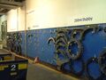
DSCF4077 A view from the riverbank of some of the 34 x 7000hL conditioning tanks. The working corridor is underground. | File:DSCF4071.JPG|One of 74 x 1500hL conical bottomed fermenters | ||
DSCF4078 Filtrox candle filter | File:DSCF4076.JPG|Equipment on the top of a fermenter | ||
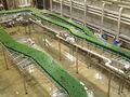
DSCF4079 Some of the 14 x 1250hL horizontal bright beer tanks | File:DSCF4077.JPG|A view from the riverbank of some of the 34 x 7000hL conditioning tanks. The working corridor is underground. | ||
DSCF4080 440mL cans of Skol coming off two can lines | File:DSCF4078.JPG|Filtrox candle filter | ||
DSCF4081 The Krones can filler and Ferrum seamer | File:DSCF4079.JPG|Some of the 14 x 1250hL horizontal bright beer tanks | ||
DSCF4082 A record week on No1 can line | File:DSCF4080.JPG|440mL cans of Skol coming off two can lines | ||
DSCF4089 Bottle conveyors with the Sander Hansen pasteuriser on the right | File:DSCF4081.JPG|The Krones can filler and Ferrum seamer | ||
DSCF4090 The 1998 Krones bottling line works at 54,000bph | File:DSCF4082.JPG|A record week on No1 can line | ||
DSCF4091 Change parts for the bottling line | File:DSCF4089.JPG|Bottle conveyors with the Sander Hansen pasteuriser on the right | ||
DSCF4092 The 16 lane APV kegging line dates from 1993 and will fill 1000 50L kegs an hour | File:DSCF4090.JPG|The 1998 Krones bottling line works at 54,000bph | ||
DSCF4093 Locator board handling is still manual | File:DSCF4091.JPG|Change parts for the bottling line | ||
[[category:Brewer & | File:DSCF4092.JPG|The 16 lane APV kegging line dates from 1993 and will fill 1000 50L kegs an hour | ||
File:DSCF4093.JPG|Locator board handling is still manual | |||
</gallery> | |||
[[category:Brewer & Distiller International Gallery]] | |||
Latest revision as of 17:55, 26 January 2022
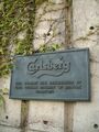
The brewery was opened in 1974
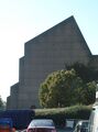
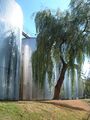
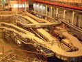
The brewery was designed to incorporate the shape of a viking longboat - the prow is the brewhouse
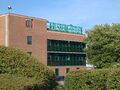
Corporate offices on site
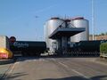
Road tanker loading bay
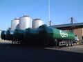
Another view of road tankers
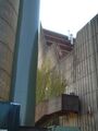
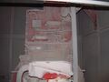
The bare concrete does present a rather austere facade
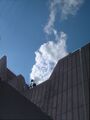
Steam issues from the viking longboat!
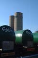
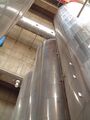
Two malt silos. One has nine 100 tonne cells and other six 200t
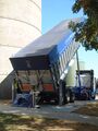
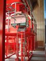
Malt wagon unloading

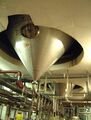
The chisel bottom of the silo cells in created by a huge conical bottom to the structure
The outfeed conveyors from the malt silos
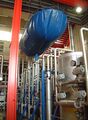
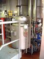
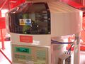
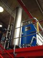
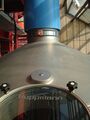
CO2 collection plant by Union Engineering from Denmark
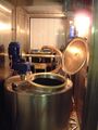
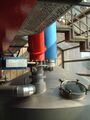
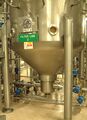
60% of the beer bitterness comes from liquid extract. It is kept warm in a Decker cabinet.
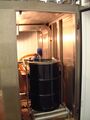
The extract is tipped from a drum into the working tank
This device slits hop pellet boxes - it was awaiting its cabinet
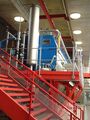
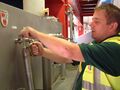
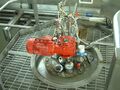
Hop pellets are fed into the hop pots. Wort picks them up and pumps the hops to the coppers
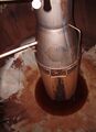
Another treatments pot
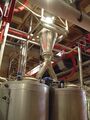
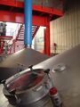
Inside the cavernous brewhouse
The malt screens are by Buhler
The Chronos Richardson malt weighers
The hammer mill within its acoustic and explosion proof box
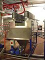
This 12 tonne Meura mash filter was installed in 1998
The wort balance tank on the Meura mash filter
The newer mash filter installed in 2002
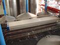
Below the mash filter showing the spent grains discharge trough
The discharge to the spent grains tanks
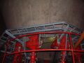
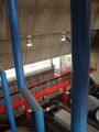
High above the brew vessels
The two mash filters are at right angles to each other
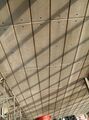
Bare concrete walls in the brewhouse
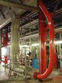
The copper calandria by Huppmann
Taking a wort sample
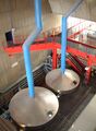
The vessel in the foreground is the whirlpool with the wort prerun vessel behind
The whirlpool vessel
The mash vessel will process 12 tonnes every two hours giving twelve 650hL brews a day. There are two mash lines
One of 74 x 1500hL conical bottomed fermenters
Equipment on the top of a fermenter
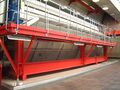
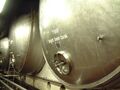
A view from the riverbank of some of the 34 x 7000hL conditioning tanks. The working corridor is underground.
Filtrox candle filter
Some of the 14 x 1250hL horizontal bright beer tanks
440mL cans of Skol coming off two can lines
The Krones can filler and Ferrum seamer
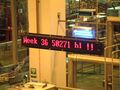
A record week on No1 can line
Bottle conveyors with the Sander Hansen pasteuriser on the right
The 1998 Krones bottling line works at 54,000bph
Change parts for the bottling line
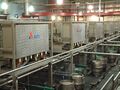
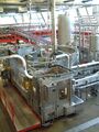
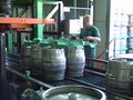
The 16 lane APV kegging line dates from 1993 and will fill 1000 50L kegs an hour
Locator board handling is still manual


